Technical Considerations on EMC
Electromagnetic Compatibility (EMC) is concerned with both the process of emission of unintentional electromagnetic energy from an electronic equipment and the ability of this equipment to function in the presence of interfering energy (immunity to the electromagnetic environment).
Sources of interference
Since natural interference phenomena do not really affect the modern equipment, the actual problems today are generated accidentally by the actual operation of the equipment. Basically, the radiated interfering signals are classified in a narrow band and broad band. Narrow band signals occupy a small portion of the radio spectrum and have the energy concentrated in a single frequency wave. However, when modulation is introduced, the narrow band signal may generate side bands of energy which may cover hundreds of kilohertz. Examples of sources for narrow band signals are radio & TV transmitters, radio transceivers, cellular telephonic equipment and Doppler radar. These sources start out with very low harmonic frequency outputs but can cause harmonic frequencies to be generated if they are used in areas which can present non-linear conditions to the RF energy through secondary transmission of these signals.
Broad band signals are those whose energy is spread over tens of hundreds of Megahertz. They are generated by narrow pulses with sharp rise times, characteristic of radars, gas discharge tubes, engine ignition systems, power line discharges, computer clocking pulses, motor brushes and switching regulators. The steepness of the pulses causes problems because the short rise times mean very high frequencies and that which may appear to be a low impedance can actually have a high inductive component and be a high impedance for the rise time.
Oscillator circuits on printed circuit boards can cause energy to be both conducted and radiated. These oscillator sources may be part of the power supply (as in switching regulators) or they may be part of the logic clock circuits. Other source of radiation could be amplifier circuits with a high slew rate, which can have very fast rise times and, if not terminated properly, can cause a large spectrum of noise.
Actually, every frequency source could be a potential source of interference and all interference signals can be coupled to the power line and conducted to the power mains, thus creating problems to other equipments connected close to the signal source equipment.
Recommendations for effective EMC design
The most efficient design will take into account from the beginning the possible presence of strong external influences which may cause the equipment to malfunction, as well as the need to limit the amount of conducted and radiated emissions which may influence other equipments. Retrofitting a solution to a design problem later, in the testing process, is costly and time consuming.
The best EMC design will keep the strong energies on board, where generated. In order to keep it “on board”, the following steps are suggested:
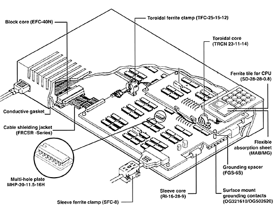
EMI and ESD can be easily controlled by proper grounding, shielding and filtering using ferrite products (cores for round and flat cables, surface mount ferrite chips, multi-hole plates for connectors, etc.), cable shielding materials (conductive tapes, shielding jackets, etc.) and grounding fasteners from KITAGAWA INDUSTRIES America. Among these solutions, filtering by using a ferrite core may be the most cost efficient measure. This method has a significant merit that it imparts insertion loss only to unnecessary noise and does not influence the line signals when used as a common mode choke.
Using ferrite cores for EMI suppression
Based on the specific magnetic properties of the Nickel-Zinc ceramic ferrite materials, molded cores, when used as EMI filters, absorb the energy of the high frequency noise on the line and dissipate it as quantities of heat. Since the electrical resistance component of the material is reduced at low levels of frequency, the ferrite cores provide very low series impedance and do not affect the normal data signals on the line.
Typical ferrite materials characteristics
The physical characteristics of the KITAGAWA INDUSTRIES America Ni-Zn ferrite materials are listed below:
| AC Initial Permeability | μiac | 650 – 1100 |
| Relative Loss Factor | tanδ /μiac | 1.30 – 2.00×10⁻⁵ @0.4MHz |
| Saturation Flux Density | Bs | 250 – 350 mT |
| Residual Flux Density | Br | 100 – 280 mT |
| Coercive Force | Hc | 16 – 55 A/M |
| Relative Temp Factor | αμr | 7 – 15×10-6 |
| Cune Temperature | Tc | 130 – 200℃ |
| Specific Resistivity | ρ | 10° Ω-cm |
| Density | d | 4.8 – 5.1 g/cm3 |
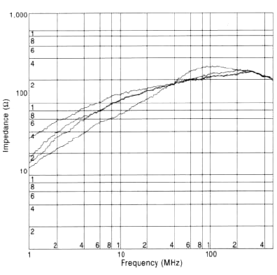
The impedance vs. frequency characteristics for several Ni-Zn ferrite materials are shown on below.
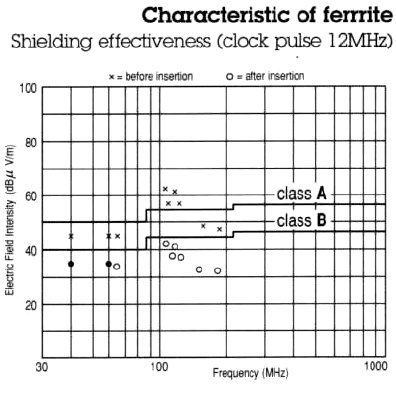
The shielding effectiveness provided at different frequency levels is shown on below.
Relationship between impedance vs. frequency characteristic and insertion loss
The impedance is dominated by the R factor (resistance), which has the main influence on the insertion loss. At higher frequencies (> 200 MHz) the impedance characteristic is reversed, due to stray capacities.
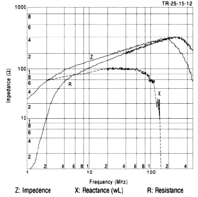
The impedance Z increases as frequency increases.

Above graph displays the insertion loss at 50 Ohms load impedance.
Finding insertion loss (attenuation, dB)

Examples of calculation:
The insertion loss (dB) = 20 LOG ((1+500)/1) = 54 dB
The insertion loss (dB) = 20 LOG ((50+500)/50) = 21 dB
When comparing Examples 6.1 and 6.3 above, it is found that, even if the same ferrite core is employed, a strikingly different damping factor will be assured if the impedance of the circuit is different. In other words, the effects of ferrite cores are increased at lower circuit impedance. It may be said, therefore, that the number of turns should be increased or ferrite cores with larger volume and higher impedance should be employed if the circuit impedance is high.
Relationship between the number of turns (windings) and impedance vs. frequency characteristic
The graphs shown in Fig 6. indicate performance curves of one to four turns from the bottom to the top, respectively. As the number of turns is increased, the impedance is enhanced, but it shown from this figure that the peaks of impedance are moved downward as stray capacities between lines are increased.
If insertion loss needs to be increased at lower frequencies, the number of turns should be increased as common mode choke so that damping may apply only without any influence upon signals.
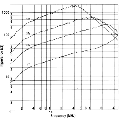
Figure 6
Common mode choke
Should ferrite cores be inserted as shown on Fig. 7, they will not only impart insertion loss to common mode noises, but also influence signals. On the contrary, and inserting method, as shown on Fig. 8, called common mode choke, does not influence signals, because magnetic fields produced by signal currents cancel each other, thereby no insertion loss being imparted to the signals. Since noise currents flow for the ground, magnetic fields with a specific direction are produced, thereby this method proved to be a convenient way to absorb noises only.
When ferrite cores are used to eliminate high frequency noises on a DC line such as a power supply line, the supply line as well as the grounding return line can be inserted through the ferrite core.
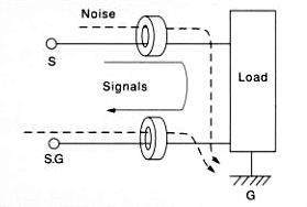
Figure 7
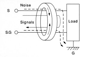
Figure 8
Difference in impedance vs. frequency characteristic between split cores and one-piece cores
The graph shown in Fig. 9 compares characteristics of separated and non-separated toroidal cores of the same size. Although impedance of a separated core is lower in the area less than 30MHz, it is similar to or slightly higher than that of a non-separated one at higher frequencies.
The merit of using the separated cores is that they may be easily mounted in an already wired cable or a cable which has been already connected to a connector and that magnetic saturation in DC occurs less frequently in separated cores than in non-separated ones when large DC current flows through a line.
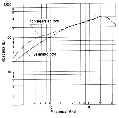
Figure 9
Typical package example
